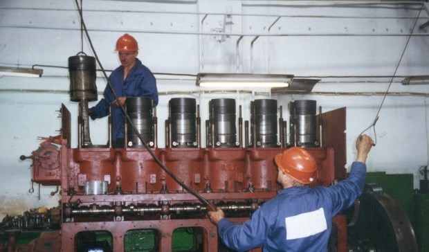
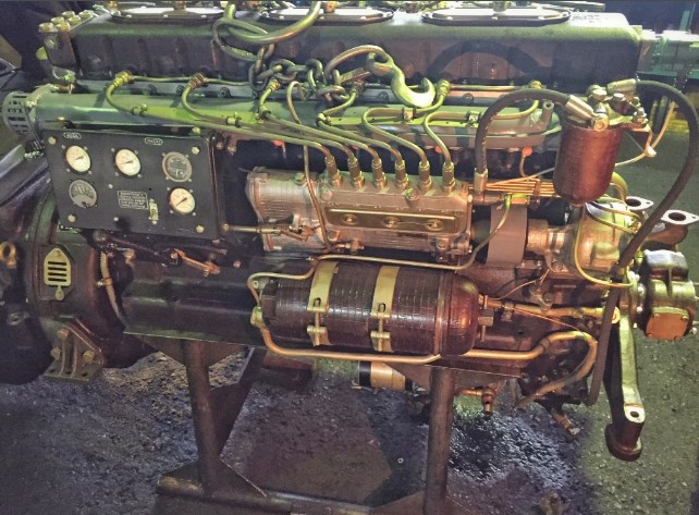
performing repair of ship engines worth considering, that the misalignment of the piston in the cylinder occurs even with a precise mechanism in the case of non-perpendicularity of the axes of the cylinder and the crankshaft. But in order to "align" the piston before aligning its axis with the axis of the cylinder, tend to "knock down" the piston in the direction of the arrow by subcutting the crank bearing on the other side. With such a sub-scoring, the mechanism is turned from an exact one into a skewed one..
Permissible deviations for non-parallelism of the connecting rod axes depending on the length of the piston pin are taken incorrectly, since with the same length of the head bearing, the length of the connecting rod in engines of different brands is different. Therefore, if the axes of the connecting rod heads are not parallel or the axes of the crank journals are not parallel to the axis of the crankshaft, the rate should be assigned depending on the length of the connecting rod, and most correctly - depending on the length (height) mechanism, since with the same connecting rod length for different engine brands, the length of the mechanism is different.
In order to align the axis of the piston with the axis of the cylinder and align the clearances, not always necessary, as recommended by rules and regulations, scrape the crank bearing from the back. It is seen, that such a subscripting does not establish a skew, but lead to non-perpendicularity of the axes of the crank bearing and the connecting rod. By scribing, the piston and cylinder axes will be aligned, but an angle is formed between the axis of the connecting rod and the axis of the cylinder and piston.
In this case, it would be more correct to scrape the head bearing instead of the crank, since the piston pin axis would move from position III to IV.
Consider imbalances for engines, having the dimensions of the crank mechanism the same with the dimensions of the 3D6 brand or close to them. Consider the cases (which in the calculations it turned out 814, and with compensation 902) misalignment with different relative positions of skewed parts and in combination of skewed parts with non-skewed.
In various sources, the installation clearance between the piston and the cylinder sleeve is recommended as a standard - 0,464 mm at the standard of the building plant 0.00105D, where D is the cylinder diameter.
When repairing ships, support and thrust bearings and their foundations are often removed., the machine is lifted and for laying the gross line it is required to restore the centerline of the shafting and to clarify the coordinates of the installation of support and thrust bearings, as well as the machine itself.
If the stern tube was not replaced during repair, then the restoration of the centerline of the shafting is usually carried out as follows:
- from the stern and bow sides of the stern tube are installed opaque plugs made of steel sheet 3-4 mm thick, with a millimeter hole in the center;
- from the outside of the stern tube, approximately on its axis, a strong light source is placed in the hood (usually an incandescent lamp around 500 Tue);
- at the intended places of bearing installation, oil seals, etc.. d. exhibit shergey with teddy bears.
Misha is arranged like this, what hole, formed by the intersection of two light transmission slits, can be moved and set according to the fixed position of the light beam. For an approximate installation of targets through the stern tube to the forward machine bulkhead, a string is pulled. The bases for the installation of the string are the centers of the front and rear ends of the stern tube.
String, stretched and calibrated along the bases using micrometer gages and compasses, is only relevant for the approximate installation of targets in relation to the sides of the vessel. The string does not provide the vertical position of the targets., since it sags. As the targets are installed along the string, the last one is removed, after which the vertical screens are installed in the light.
The light line is pierced at night., to avoid light scattering, as well as errors due to deformation of the case, arising from the one-sided heating of it by the rays of the sun.
The piercing of the light line is considered complete., when it will be possible to find such a position of all the targets, in which light is visible along the entire line. According to the obtained coordinates of the axial line of the shafting, installation drawings of foundations and bearings are produced. All this, starting with the manufacture and installation of shergen and targets and ending with the capture of the light beam and its coordination with respect to the ship's hull, pretty hard, and most importantly, takes a lot of time.

